Vacuum Tube Digital Clock
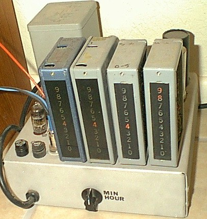
I'm taking a long break from working on the new cabinet for the tube clock. Here is the new main chassis. This part will face backwards, and the display chassis (with the hours and minutes units) will be remote and face forward. Wait till you see the cabinet...it'll make sense then.
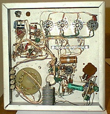
And the underside of the chassisbefore it was complted:
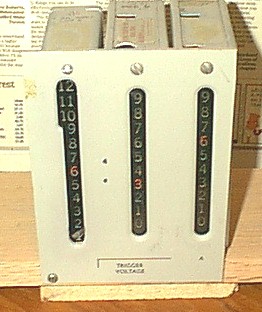
This is the remote unit which displays the time, hours and minutes:
Here's the working clockw when it was still in the Beckman chassis:
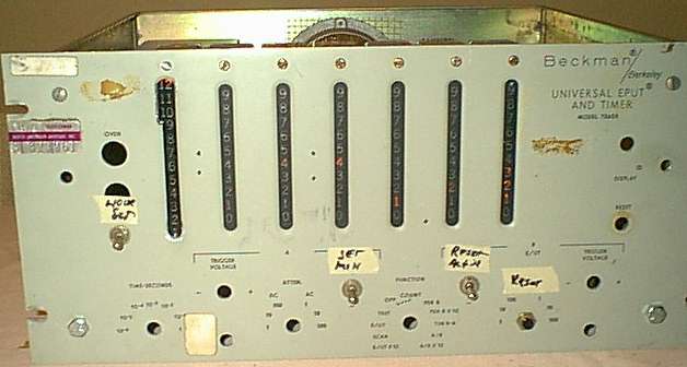
In the 1950s, before the invention of the Nixie display tube, electronic equipment designers had to resort to some rather crude methods to display numeric information. This is a Beckman/Berkeley counter/timer, circa 1962 (approx). I have modified it to be a digital clock.
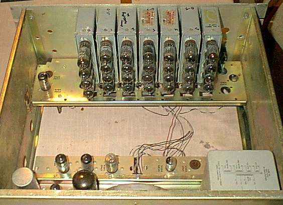
I have stripped most of the circuitry from the counter, leaving the power supply, input amp/shaper, reset circuit, and the decade counter units. I modified the counters as needed to work as a digital clock, using the 60 cycle/second line frequency as a time source. The line sine wave is modified into a pulse, then fed to the counter stages. The second, fourth, and sixth stages are modified to count from zero to five, the modification is simple, disconnecting the last flip-flop. The seventh stage counts from one to twelve, this was a much more complicated mod, requiring the addition of two more neon lights, and adding more decoding circuitry.
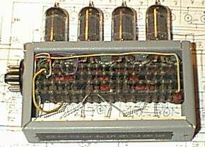
This is a decade counting unit. Each 5963 tube is a flip-flop. Each number is displayed by lighting a neon lamp. The counter has some feedback loops to bypass six of the sixteen counts, so it will act as a decade counter.
The modified hour counter main changes are the elimination of the 3rd-2nd and 4th-2nd feedback loops, the addition of two more lights, and the added decoding for the first 8 counts (using three instead of two binary inputs). See schematics for all thee types of modules (normal decade, six, and 12 count).
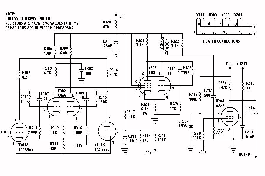
clock1.jpg schematic of pulse generator
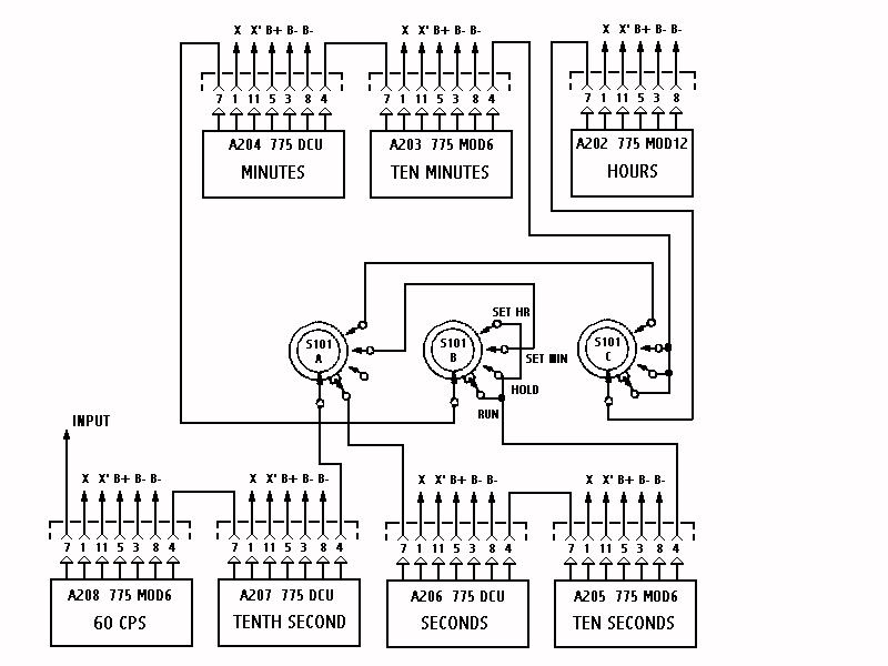
clock2.jpg schematic of display wiring
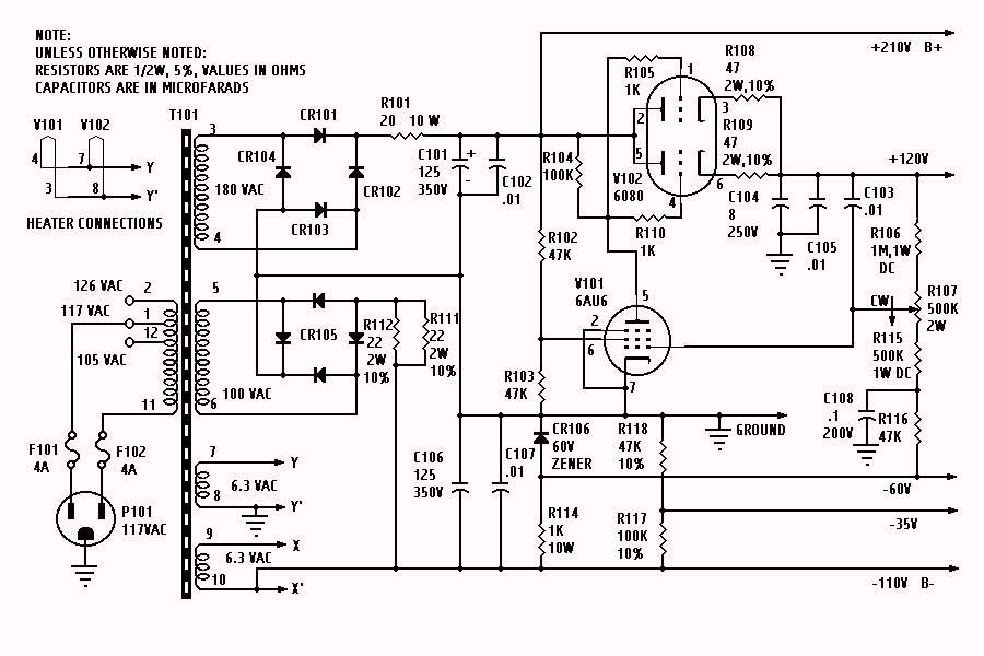
clock3.jpg schematic of power supply